Phase Shift Keying
|
In Phase Shift Keying (PSK) incoming data bits vary the phase of a cosine carrier while keeping a constant carrier frequency. In N-PSK, the cosine can assume one of N possible phases. In Quadrature Amplitude Modulation (QAM), both the phase and amplitude are varied.
A specific phase/amplitude state (A, Φ) may be illustrated on a polar plot called a constellation
diagram as shown at right.
When all available (A, Φ) points are plotted, the complete constellation diagram defines the characteristics of each of the following modulation types.
|
 |
Binary Phase Shift Keying (BPSK)
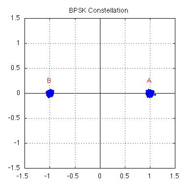
| In Binary Phase Shift Keying (BPSK or 2-PSK), there are two possible phases
which the carrier can have at a given time, as shown at right on the characteristic
constellation having two carrier states. The two phases are labelled
{A,B} corresponding to either Φ=0 or Φ=180 degrees and the same amplitude. The presence of noise in
a real system causes these otherwise well-defined points to appear
with some uncertainty as shown.
In BPSK there are two possible phases,
and therefore one bit (0,1) of information conveyed within each time slot. The rate
of change (baud) in this signal determines the signal bandwidth, and the
throughput or bit rate for BPSK equals the baud rate. For example, if phase changes occur 600 times per second then this is a 600 baud modem conveying one bit per change or 600 bits per second.
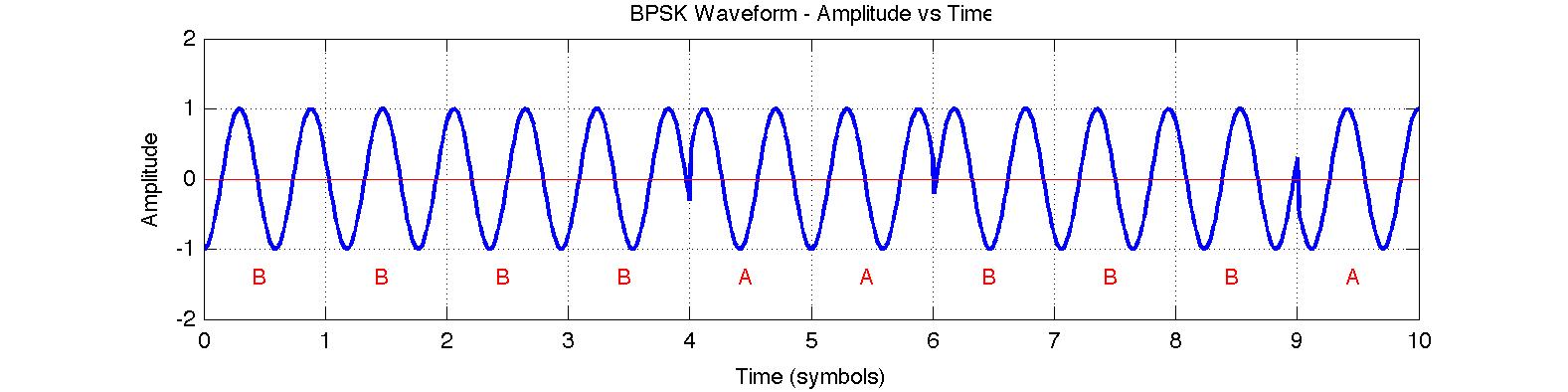
In the time domain waveform below, it can be noted that abrupt changes in phase result in sharp transitions that
would be filtered out to give a smoother bandlimited waveform before being transmitted.
|
 |
 |
Transmitting Data Using BPSK
|
In BPSK, information is generally conveyed through phase variations since absolute phase cannot be established
upon reception. In each time period, the BPSK phase can change (or not) by 180 degrees while the amplitude remains constant as seen in the above waveform. Data bits (0,1) may be represented by a change in phase (1) or no change in phase (0).
This goal may be realized in hardware before modulation by using non-return to zero (mark) (NRZ-M) encoding on the input data. In the circuit at right, on every clock edge the output changes if the input bit is 1 and the remains unchanged if the input bit is 0. Let the BPSK modulation state be 'A' if the output is 1 and 'B' if the output is 0.
Using NRZ-M encoding, the first transition at time t=1 in the above BPSK waveform is B-to-B which is "no
phase change" representing the data bit 0.
|
 |
Quadrature Phase Shift Keying (QPSK)
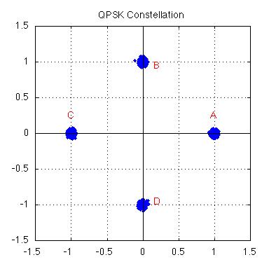
| In Quadrature Phase Shift Keying (QPSK or 4-PSK) there are four possible phases
which the carrier can have at a given time, as seen in the constellation at right.
The four phases are labelled {A,B,C,D} corresponding to one of {0,90,180,270} degrees.
The term quadrature emerges as the QPSK constellation may be described as two BPSK signals (horizontal and vertical) modulated using cosine or sine respectively and called the in-phase and quadrature components of the QPSK signal.
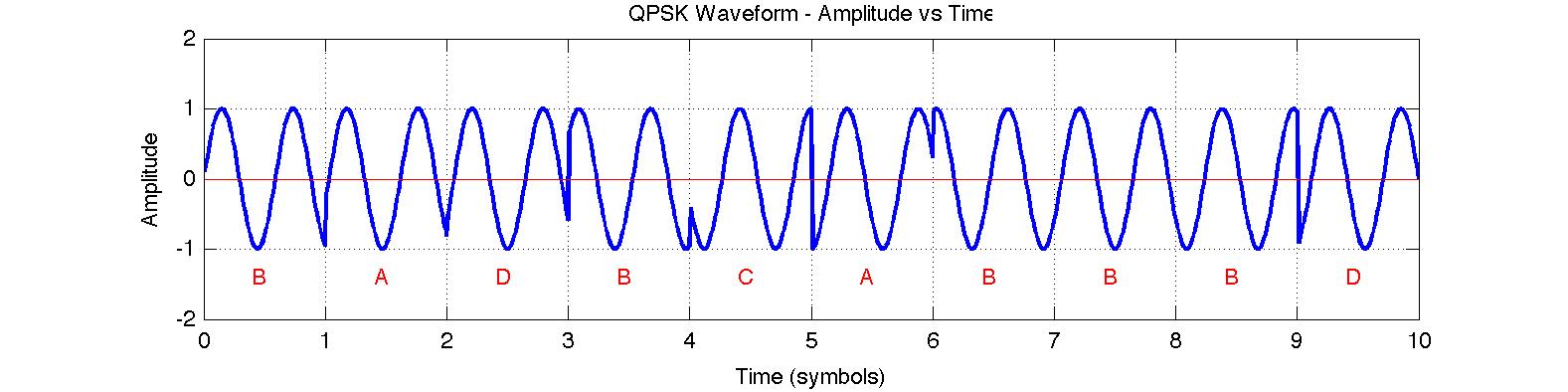
In PSK, information in conveyed through phase variations, since absolute phase cannot be established. In each time period, the phase can change once while the amplitude remains constant. In QPSK there are four possible phases,
and therefore two bits of information conveyed within each time slot. The rate
of change (baud) in this signal determines the signal bandwidth, but the
throughput or bit rate for QPSK is twice the baud rate.
For example, an ITU-T V.22
modem uses QPSK to send data at 1200 bits per second over a dial-up phone line. In this case, the carrier phase
changes only 600 times per second to ensure an acceptable (small) bandwidth and this is a 600 baud modem conveying two bits per change.
|
 |
 |
Transmitting Data Using QPSK
|
Each of the four possible phase changes is assigned a specific two-bit
value, or dibit. In the V.22 modem, for example, the relationship
between phase changes and dibits is given by the table at right.
Using this table, the first transition at time t=1 in the above QPSK waveform is B-to-A which is a positive phase change of 270 degrees on the constellation and represents the two bits "11".
|
|
PHASE CHANGE (Degrees)
|
Example state change
|
Dibit
|
|
0
|
A-to-A
|
01
|
|
90
|
A-to-B
|
00
|
|
180
|
B-to-D
|
10
|
|
270
|
D-to-C
|
11
|
|
8 Phase Shift Keying (8-PSK)
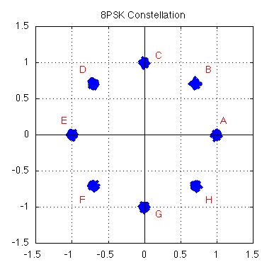
| In 8-PSK there are eight possible phases
which the carrier can have at a given time, as shown at right on the characteristic
constellation for this modulation type. The eight phases are labelled
{A,B,C,D,E,F,G,H} corresponding to phase vectors equally separated by 45 degrees.
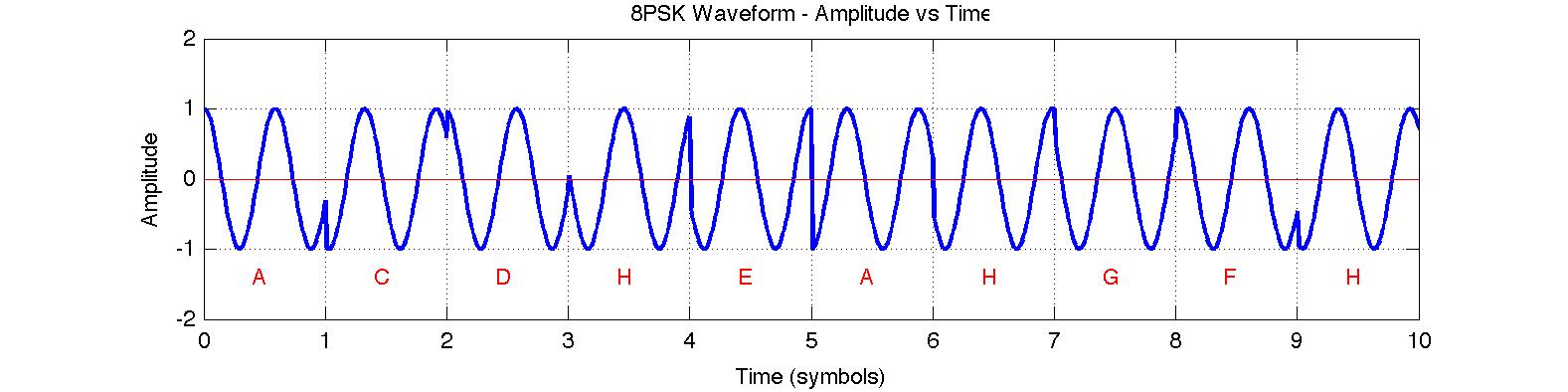
In PSK, information in conveyed through phase variations, since absolute phase cannot be established. In each time
period, the phase can change once while the amplitude remains constant. In 8-PSK there are eight possible phases,
and therefore three bits of information conveyed within each time slot. The rate
of change (baud) in this signal determines the signal bandwidth, but the
throughput or bit rate for 8-PSK is three times the baud rate.
For example, if the carrier phase of an 8-PSK modem changes 600 times per second (600 baud) then the bit
rate is 1800 bits per second. The 8-PSK modem is typically used in satellite transmissions where data rates can
exceed 100 Mbits per second.
|
 |
 |
Quadrature Amplitude Modulation (QAM)
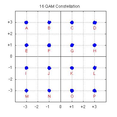
| In Quadrature Amplitude Modulation (QAM), there are changes in both phase and amplitude.
In 16-QAM there are sixteen possible phase/amplitude states
which the carier can have at a given time, as shown at right in a distinctive square
constellation. The sixteen states are labelled
{A through P} corresponding to the phase vectors describing each state.
As in PSK, information in conveyed through phase variations, since absolute phase cannot be
established; however, absolute amplitude can distinguish between two states with the same phase (such as G and
D). In each time
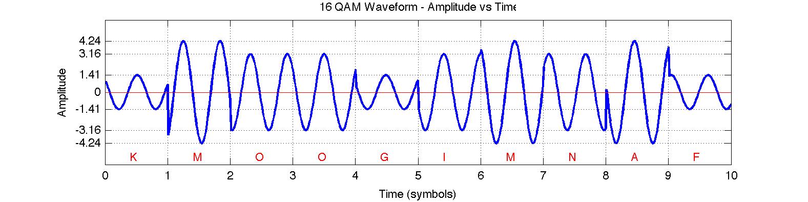
period, the phase and/or the amplitude can change once. In 16-QAM there are sixteen possible
states and therefore four bits of information conveyed within each time slot. The rate
of change (baud) in this signal determines the signal bandwidth, but the
throughput or bit rate for 16-QAM is four times the baud rate.
For example, an ITU-T V.22bis modem uses 16-QAM to send data at 2400 bits per second over a dial-up phone line. In this case, the carrier
phase/amplitude changes only 600 times per second to ensure an acceptable (small) bandwidth and this is a 600 baud
modem conveying four bits per change.
|
 |
 |
Continue with the 16-QAM Decoding Tool.
Data Scrambling
Scrambling is the process of randomizing the bits in a message in such a way that the message can later be descrambled or
restored to the original bits. While most commonly associated with cryptography and secrecy, the scrambling operation in this case is intended to improve modem performance and the scrambling parameters form part of published modem standards1. The
required scrambling and descrambling operations are readily accomplished using shift register circuits.
Scrambling is generally used in PSK and QAM modems because randomizing the data stream ensures frequent transitions and avoids the potential for transmitting a constant carrier with no phase changes. For example, the unscrambled data stream 01010101... could produce a constant phase signal (e.g. AAAAAA...) in a BPSK signal. For QAM modulation, scrambling ensures that every constellation state is visited regularly to ensure an average signal power that is not dominated by the higher amplitude states.
While scrambling is a necessary and desirable component of a PSK modem, the operation has consequences for
error control. Consider a typical descrambling circuit as shown below, and a single bit error E(x) that occurs during transmission. As a single (errored) bit passes through this circuit it is repeated several times at the
output; consequently, the single bit error becomes a burst error spanning the length of the descramber circuit.
This effect must be considered when choosing an error control method for use in a system that employs data
scrambling.
1For example, the scrambling polynomial used in V.22 modems is: X = 1 + X-14 + X-17 as found in ITU-T Recommendation V.22
Error Control with PSK signals
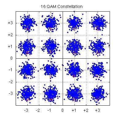
| As the noise level in a channel increases, it becomes increasingly difficult to distinguish between
states in a PSK modulated signal. Consider the (noisy) 16-QAM constellation at right in which the signal states are poorly defined and it is quite likely that during demodulation a state will be assigned to the wrong constellation point.
In PSK/QAM, bits are encoded as state changes and the effect of errors is magnified because one bad state assignment leads to two bad state changes. For example, the state sequence A-B-C contains the changes A-B and B-C; however, if the symbol B is interpreted as F, then the sequence A-F-C contain the
two changes A-F and F-C. Consequently a single 'symbol error' leads to multiple bit errors.
When combined with the presence of a descrambler that speads even a single error over several bits, it is clear
that single bit errors are extremely unlikely at the output of a PSK demodulator and burst errors can be expected whenever a symbol error occurs.
Effective error control strategies must be based on the expected errors in the communications channel, including the modulation methods in use. Ideally, some form of error control could be implemented within the PSK modem to reliably establish the phase states and to augment other layers of error correction.
|
 |