|
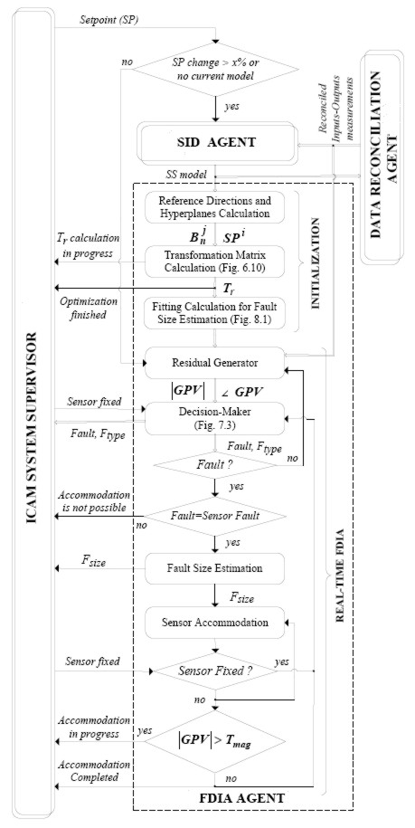
UNB's Fault Detection, Isolation and Accommodation Agent The basic idea of fault detection, isolation and accommodation is shown in the schematic diagram in Figure 1: First, a standard control system configuration is shown, with blocks CONTROLLER, ACTUATOR, PLANT and SENSOR. A reference input or set point is supplied to the control system, and the controller action should maintain the plant output at or close to that set point. As indicated, the actuator or sensor may experience a fault which may prevent the control system from performing as designed. Faults might include an actuator sticking so it can no longer provide the desired input to the plant, or a sensor developing a bias (a step error) or starting to drift (a ramp error). The FDIA component has access to the controller and sensor outputs, and, as illustrated below, generates a diagnosis (e.g., "sensor 3 bias fault, size = - 19.482 %") which is sent to the ICAM Supervisor. If a fault is detected and isolated the Supervisor informs the operator for his/her attention; also, if the fault is in a sensor then the Supervisor can correct the sensor reading accordingly (e.g., subtract the bias value or drift from that sensor reading).  Figure 1. FDIA Schematic
 Figure 3. FDIA First Illustrative Example Finally, the ability of the FDIA Agent to determine the size of faults and accommodate them is demonstrated as follows. Scenario: a - 7% bias fault is applied to the treator water volume sensor (S3) at t = 60 sec.; then, after this fault has been completely accommodated, a + 1%/min. ramp fault is applied to the separator liquid volume sensor (S1) at t=500 sec. This is a complex scenario, so bear with us; again, we want to go beyond a simple "academic case". 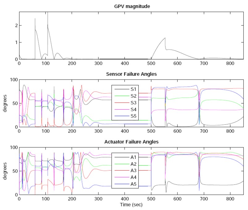 Figure 4. FDIA Second Illustrative Example First, looking at the GPV magnitude plot we observe that |GPV| makes a step jump at t = 60 sec., so detection is essentially instantaneous. The S3 angle swings rapidly towards zero, so isolation could be asserted within a few seconds; however, the momentary small value of |GPV| at about 80 sec. causes a transient in this angle, so the FDIA Agent conservatively waits until t = 108 sec. to implement accommodation, using the excellent fault size estimate of - 6.98 %. The |GPV| repeats the large fast transient as at 108 sec., but the FDIA Agent ignores that, "knowing" that this is due to accommodation. The |GPV| becomes very small until just after t = 500 sec., at which time it starts to ramp up, providing the signature that a ramp fault has occurred. The S1 angle approaches zero slowly (the liquid-level dynamics are very slow); at t = 553 sec. isolation is achieved and accommodation implemented, so after second transient |GPV| decreases indicating a return to normal operation. Of course, the fact that sensor faults are being accommodated means the operator should see to it that the sensors are fixed or replaced. Obviously a more user-friendly display of the FDIA Agent's diagnoses must be provided. As a rudimentary idea, the diagnosis produced after a bias fault was applied to the treator vapor outflow valve (A5) at t=60 sec. is shown in Figure 5. We observe that for a few samples after the fault the FDIA Agent is isolating the fault (waiting for the GPV angle to be unambiguous), and briefly in that interval there is a one-time claim that S5 is faulty; after that, the fault diagnosis is permanently correct. 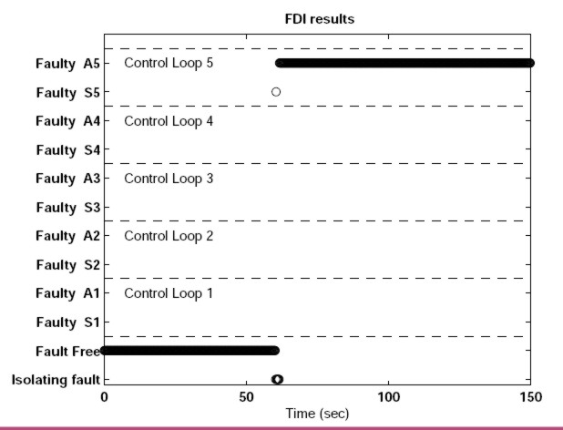 Figure 5. FDIA Preliminary Display This FDIA Agent development is the result of Dr. Maira Omana's MScEng and PhD research. For the most recent conference paper see "Fault Detection, Isolation and Accommodation Using the Generalized Parity Vector Technique", Proc. IFAC World Congress, Seoul, Korea, 6-11 July 2008 -- download HERE This part of the UNB PAWS effort has been completed and delivered. Return to the UNB PAWS Home Page Information supplied by: Jim Taylor Last update: 16 November 2009 Email requests for further information to: Jim Taylor (jtaylor@unb.ca) |