
In general, convolutional coding techniques are applied to very long messages, such as the continuous stream of data from a satellite television transmiter. A fast approach to applying bit correction dynamically during reception is required. The method of Viterbi Decoding is widely used to decode and to correct errors in convolutionally encoded data.

In this section, it is assumed that a data stream has passed through the above circuit to yield a series of two bit (dibit) symbols representing the data. It is now necessary to examine the incoming bits and to extract the original data. Of course, the symbols received may not be exactly the same as those which were originally transmitted.
The problem is clear if the symbols are simply accepted as received, as shown below. While the original symbols defined a continuous path through the trellis, the presence of errors means that now there is no obvious continuous path through the trellis. The message bits (?) cannot be determined until such a path has been found. It is expected that the path found will exactly match the original despite the errors which have occured.
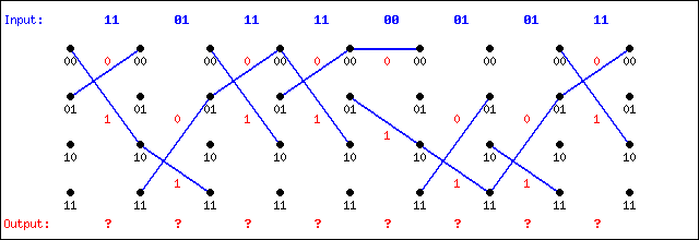
It is necessary to reconstruct a continuous path from the above information. The "best fit" path will be the one which best matches the above data, deviating only as required to establish continuity. The available resources to establish this path are the four possible symbols and the corresponding eight possible state transitions:
| Available elements to establish a continuous path | |||||||||||||||
Proceeding by trial and error to find the "missing symbols" presupposes that the location of the bad symbols was known and greatly oversimplifies the decoding process. Perhaps the symbols leading up to the "obvious" break in the path are themselves incorrect. In general, the exact location of any bad symbols cannot be known in advance. In practice, a systematic approach to identifying the best path through the trellis can be employed to correct errors automatically as they occur.
At each time interval, the (5,7) encoding circuit can have only four possible states (00,01,10,11), although many alternate paths may have led to those four states. Each state in the circuit can lead to one of two states in the next time interval. Conversely, a given state can be arrived at from one of exactly two states from the previous time interval.
In other words, exactly two incoming paths always lead to each of the four states. In general, one of those two incoming paths will have the lowest error up to that point in the trellis. By choosing the 'best path so far' and moving on to the next stage, the overall best path will be the one with the smallest 'cumulative error' at it traverses the trellis.
| Step 1 - The process begins at the start of the path, where it is always assumed the circuit begins at state 00. From here, only two paths are possible. Since the first received symbol is ' 11', the lower path (11) involves an error of 0, while the upper path (00) involves an error of 2 bits. These two values are recorded on the trellis for the next step. Any further progress along either path will add to these errors. | 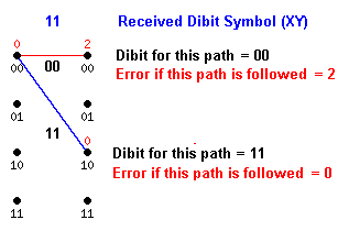 |
| Step 2 - Four paths are defined leading to the next stage, two from each of the incoming states from Step 1. The error associated with a given path segment depends on the actual symbol ' 01' received, as compared to the symbol defined for that segment. Here, the corresponding dibits are shown superimposed on each candidate path segment, and the cumulative error is shown for each endpoint. Any further progress along a path will include and possibly add to the errors recorded here on the trellis. The best path so far appears to be the lower path which still has zero error. | 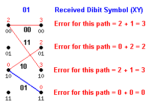 |
| Step 3 - Eight paths are defined leading to the next stage, two from each of the four incoming states. The error associated with a given path segment depends on the actual symbol '11' received, as compared to the symbol defined for that segment. Each path segment is shown with its corresponding dibits, and the cumulative error for each path is computed; however, where two paths arrive at the same state, only the one with the lowest cumulative error is retained, and the other is discarded. For example, the topmost path arrives at state 00 with a cumulative error of 5, but another path leads to this same state with a cumulative error of 2. The second path is retained and 2 is recorded, representing the best path to arrive at this state. The best overall path is uncertain at this point since there are two states with error 1 (of course, an error in the received data has just occurred). This problem is expected to be resolved as the decoding continues. | 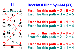 |
Continuing... - At each successive stage, the four best path errors are kept, four non-productive paths are discarded, and the overall correct path is expected to emerge from the computations...
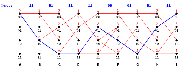
At the far end of the trellis there is one path which gives the lowest cumulative error (2), and which corresponds to the correct data. The value (2) reflects the fact that two bit errors were corrected along this path. This path can then be traced back and is shown highlighted. Paths to each of the possible endpoints can also be traced by inspection of the above trellis.
Note that a better path seemed to be emerging at stages 'E' and 'F' when the uppermost path had a cumulative error of 1. This potential path eventually lost out to the best path, but there was no clear winner until stage 'I'. The final path cannot be traced until all possible paths have been explored.
Occasionally, two paths may arrive at the same state with equal weights, and it is impossible to choose one over the other. Note that in stage 'F' two paths arrive with weight 3 at state 11. The result is two equally-likely paths which may be followed to reach this point. The same happens at state 01. In practice, one line or the other can be chosen randomly and the resulting path might eventually die anyway (as in this example), but if the best path through the trellis is uncertain, there will likely be an error in the recovered message bits.
The EE4253 Online Viterbi Decoder is available to explore bit correction in short messages using Viterbi decoding.
The Viterbi Decoding algorithm chooses the best-fit path through the trellis, correcting for multiple bit errors as the received data arrives.