Related references to this error control approach include "Trellis Coding", "Viterbi Decoding", and "Turbo Coding".

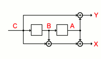
Circuit Description - The circuit consists of two D-Flip-Flops connected in series with a common clock (not shown). Data arrives at point C and each bit passes through points C and B and A in three clock periods. The output bits X and Y are formed by exclusive-OR gates as shown, such that X=C+B+A and Y=C+A.
Defined by Connections - The way in which the output bits are generated defines a particular convolutional coding circuit. In this case, the connections defining X and Y can be described as binary values 111 for X=C+B+A and 101 for Y=C+A. The corresponding generating polynomials in decimal are [5,7].
Constraint Length (K=3) - Because the output bits (XY) are a function of three bits (ABC) being the incoming bit and the two previous bits, we define a constraint length K equal to 3.
Coding Rate (R=1/2) - For each bit arriving at point C, two bits (XY) are transmitted. In practice, a circuit at the output would switch quickly between X and Y to transmit an output bitstream at twice the rate of the input bit stream. Twice as many bits emerge from the circuit as enter at point C. In common with other error control techniques, convolutional coding involves increasing the length of the original message. A coder such as this which doubles the number of bits is called a "rate one half" coder. In general, a 1/N rate code leads to a proportional length increase by N times the data bits.
Combinatorial Circuit Analysis - There are eight possible conditions for the three bits (CBA). Each combination leads to one pair of bits for the outputs (XY), as summarized in the table below.
C B A = X Y ----------- 0 0 0 = 0 0 0 0 1 = 1 1 0 1 0 = 1 0 0 1 1 = 0 1 1 0 0 = 1 1 1 0 1 = 0 0 1 1 0 = 0 1 1 1 1 = 1 0 |
Since the bits (CBA) represent the most recent three bits to enter the circuit, the outputs (XY) produced whenever a new bit arrives depend on the new bit (C) and the two previous bits (BA). This observation is key to the performance of the circuit as an error correction scheme.
Sequential Circuit Analysis Since the bits at B and A are defined by a shift register circuit fed from input C, the stored bits (BA) cannot jump arbitrarily from one state to another. For example, if the state (BA) of the flip flops is currently 00, it will change to 10 if the new bit is '1' (00 --1-> 10), and will remain 00 if the new bit is '0' (00 --0-> 00). Significantly, the flip flops could never change directly from 00 to any state except 00 or 10. Similarly, for each of the other states of the two flip flops, only two transitions are possible. The state diagram for this circuit is shown below. (The exclusive-OR gates do not play any role in this state diagram.)
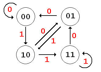
The behaviour of the two bit shift register can also be summarized graphically as shown below in a trellis diagram which shows the four possible states (BA) and the two possible transitions from each state when a new bit (C) arrives. In each case, the lower path is followed for a input '1', and the upper path for an input '0'. (The exclusive-OR gates do not play any role in this trellis diagram.)
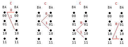
The effect of the exclusive-OR may now be included. Each three-bit condition (CBA) is associated with a unique two bit "symbol" (XY), the behavior of the circuit in time can be summarized in the table below. As as each new bit arrives one of two possible two bit "symbols" is generated as a function of the bit (C) and the shift register state (BA).
THIS -------------> NEXT STATE STATE BA -C--> CBA=(XY) next BA ------------------------- 00 -0--> 000=(00) ===> 00 00 -1--> 100=(11) ===> 10 ------------------------- 01 -0--> 001=(11) ===> 00 01 -1--> 101=(00) ===> 10 ------------------------- 10 -0--> 010=(10) ===> 01 10 -1--> 110=(01) ===> 11 ------------------------- 11 -0--> 011=(01) ===> 01 11 -1--> 111=(10) ===> 11 ------------------------- |
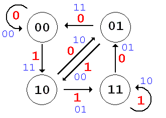
The trellis diagram can now show the overall effect of the convolutional coder. In this figure the arrival of each new bit is now associated with a symbol (XY) to be transmitted. In each case, the lower path is followed for an input '1', and the upper path for an input '0'.
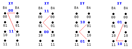
Assume the circuit starts in the state 00. When the first '1' arrives, the bits CBA=100 produce the bit pair XY=11. When the circuit is clocked, the new state BA is 10. This process can be shown as
BA -C--> CBA=(XY) next BA
00 -1--> 100=(11) ---> 10
The two bit "symbol" 11 will be transmitted in place of the single incoming data bit. This is a 1/2 rate encoder since two bits result from each incoming bit. (Two bits together are often called a "dibit")
The state BA is now 10 when the next bit arrives.
The entire process is summarized below to show the state of the circuit (BA) and the output symbols (XY) in time as each data bit (C) arrives. After the final data bit, the circuit can be put back into the state 00 by sending extra zeros. This also ensures that an error could be corrected in one of the final data bits.
BA -C--> CBA=(XY) next BA
|
The resulting message is transmitted as:
A Trellis Diagram It can be observed that during the above encoding process, the circuit passes through states (BA) shown on the Trellis Diagram shown below. Since for each incoming bit there are only two possible branches to a new state, the trellis diagram illustrates how the convolutional coder serves to constrain potential paths as time moves from left to right. A distinct path through the trellis can be traced as a function of the incoming bits.
| 1 | 0 | 0 | 1 | 1 | 1 | 0 | 1 | 1 | 0 | 0 | |
| Incoming Bits | |||||||||||
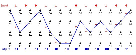
The exclusive-OR circuitry maps a two-bit symbol (XY) onto each of the above state transitions. The trellis diagram can now be redrawn to show the symbols associated with the above states.
| The continuous path through the trellis defines the transmitted symbols. | |||||||||||
By tracing the continous path through the trellis, the dibit symbols are determined. Note the the transmitted data does not directly incorporate the original data bits. Instead, the new bit stream with double the number of bits describes a distinct path through the trellis from which the original data bits can be extracted.
| Incoming Bits |
 |
| Transmitted Symbols |
Upon reception, it is necessary to reconstruct the original bitstream essentially by retracing the above path from the symbols which are received. Error correction is possible because an errored symbol will cause a detectable deviation from the correct path. The remaining symbols may be then used to reconstruct the most likely correct path and consequently, the correct bitstream. This process is explored in the next section.
The EE4253 Online Convolutional Coder may be used to explore encoding short messages using convolutional coding.
Convolutional coding is fast, efficient, and readily implemented in hardware. It is the method of choice for error control in many applications.